Hardware
Overview
Shepherd is a HW/SW solution and this section describes the key interfaces of the shepherd hardware that are relevant to users.
Each shepherd observer consists of four key components:
The BeagleBone is a Single Board Computer, handling synchronization, data storage and hardware control
The shepherd cape contains the harvester- and emulator-circuitry and all other fixed hardware parts
an optional harvesting adapter can be used to interface a harvesting transducer (e.g. solar panel) to the harvesting-port on the cape
The target pcb connects a sensor node (e.g. a microcontroller with radio) to the emulator-circuit
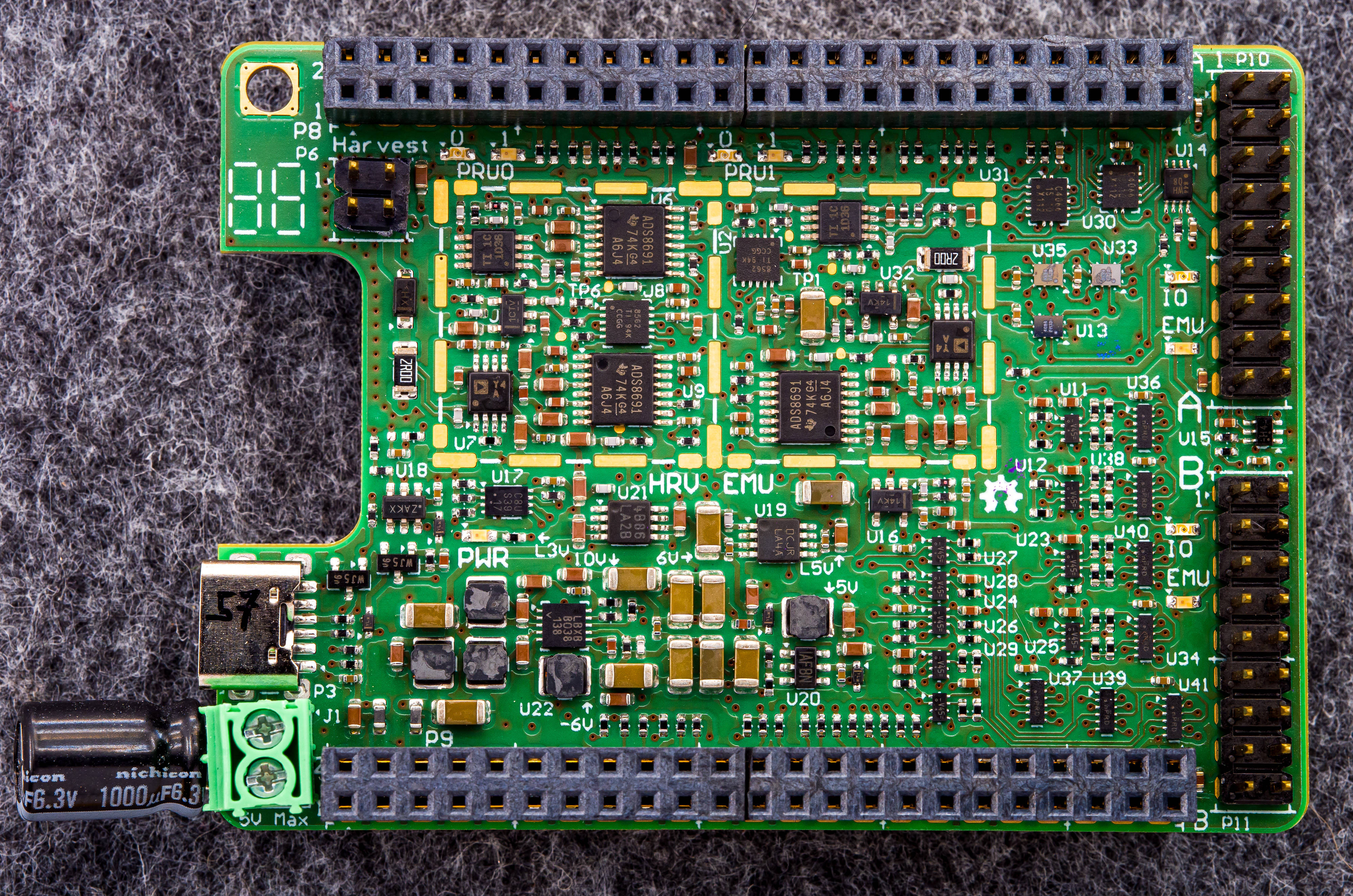
The Cape
This custom PCB contains the analog frontend for harvesting & emulation operations. The included components and features are:
the emulator and harvester consist of a purpose-fully chosen combination of low-noise and high-speed DACs, ADCs and Instrumentation-Amplifiers
both circuits can handle 0 - 5 V with up to 50 mA current
LSB is ~ 200 nA and ~ 20 uV for voltage- and current-measurements
two target-ports for the emulator, user choice
two parallel power rails available for the targets (one with current measurement, switchable)
one default target with a nrf52-module (see below)
9 GPIO-Channels between target and system (fully monitored), switchable direction on some channels
4 programming-lines to each target for JTAG, SWD or SBW
level translated gpio is designed to prevent the transfer of energy. it is also possible to completely disconnect the target
watchdog to recover from hangups during unsupervised operation
screw-in power-socket or type-c connector
eeprom to store calibration and cape-config
References
/hardware-directory: contains cape, housing and additional design-files
Harvesting Port
The harvesting port connects to any type of harvester, e.g., a solar panel or piezo-electric element to the shepherd hardware. Some transducers need some external circuitry to work properly or for protection. By keeping this part of the hardware separate from the main shepherd cape, we allow to easily connect various types of harvesters, without having to change the complex and expensive main cape.
Pin |
Description |
|---|---|
1 |
Ground |
2 |
Voltage sensing input of harvest-circuitry |
3 |
(optional) custom voltage from spare DAC |
4 |
Current sinking input of harvest-circuitry |
Harvesting Sources
Examples of tested and deployed energy harvesting sources.
Solar
Name: Anysolar - IXOLAR - SM141K06L
Source: Light
Operation: 4.15 VDC open, 184 mW Max, 3.35 V Pmpp, 58.6 mA Short
Price: 4.80 € 1x, 3.47 € 100x
Link: https://www.digikey.de/product-detail/de/anysolar-ltd/SM141K06L/SM141K06L-ND/9990462
Piezo
Name: Mide - S128-J1FR-1808YB
Source: Mechanical Vibration
Operation: 23.2 VDC, 16 mW
Price: 64,77 € per Module
This specific transducer needs an adapter with
full bridge rectifier for the transducer (with low voltage drop)
resistive voltage divider for max 5V v_sense (MOhm-Range)
Target Port
Shepherd provides two identical generic interface-ports to connect any type of cyber-physical system. These can be supplied by emulated energy traces, while tracing its state via GPIO and UART output.
The target pcb connects to the shepherd cape via the dedicated headers P10 & P11 on the right side of the board.
Pin |
Description (Rx/TX always with reference to Observer) |
|---|---|
1 |
Ground |
2 |
Emulator-Output V_Target |
3 |
GPIO0, RX & TX (Group1) |
4 |
GPIO1, RX & TX (Group1) |
5 |
GPIO2, RX & TX (Group1) |
6 |
GPIO3, RX & TX (Group1) |
7 |
GPIO4, always RX |
8 |
GPIO5, always RX |
9 |
GPIO6, always RX |
10 |
GPIO7, always RX, also UART-RX to BBone UART1 |
11 |
GPIO8, RX & TX (Group2), also UART-TX to BBone UART1 |
12 |
BAT OK, always TX, generated by PRU on BBone |
13 |
Program1-CLK - Clock for remote programming (SWD, SBW) or JTAG-TCK |
14 |
Program1-IO - Data for remote programming (SWD, SBW) or JTAG-TDI |
15 |
Program2-CLK - Clock for remote programming (SWD, SBW) or JTAG-TDO |
16 |
Program2-IO - Data for remote programming (SWD, SBW) or JTAG-TMS |
17 |
+3V3, use for any additional infrastructure circuitry |
18 |
Ground |
Notes:
GPIO is always voltage translated and the direction is switchable in groups when noted in table.
Pin 17 provides regulated 3.3V to supply any additional circuitry independent of the energy-tracing. This could be used to power, for example, a mosfet controlled debugging LED.
Pins 10 and 11 expose the level-translated signals to UART1 on BeagleBone. They can be used to trace UART messages from the target sensor node.
Pins 3 to 11 are (level-translated) connected to the low-latency GPIOs that are sampled by shepherd software for GPIO tracing.
Pin 12 is tied to the virtual power source model and signals a power-good.
Pins 13 to 16 (level-translated) are used to program/debug a connected sensor node with SWD, SBW or JTAG. This enables support for a wide range of microcontrollers.
The header is symmetrical and therefore basically safe to reverse - so errors should not result in broken hardware.
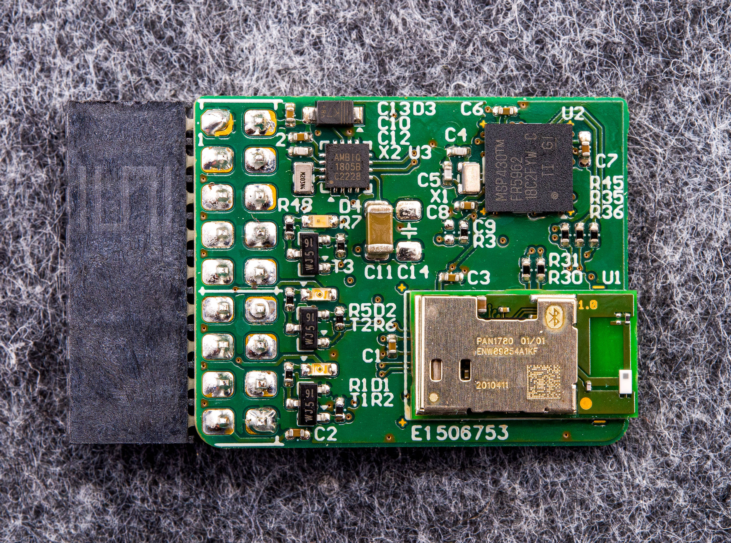
nRF-Target
This is shepherds current main target, hosting a nRF52 and MSP430, similar to the Riotee platform. Unfortunately the Riotee-SDK is not completely compatible for now, as the target is missing the hysteresis-function for the power-good-signal, which requires two pins.
The components and features are:
MCU1: nRF52840
MCU2: MSP430FR5962, 16 MHz, 128 kB FRAM, 8 kB SRAM, 68 IO, 12 bit DAC
shared GPIO, Chip2Chip / SPI, LEDs, I2C RTC
over-voltage protection for V_LV (max 3.9V)
two debug LEDs with separate supply
one self-powered LED to “burn” energy
io pins not interfering with RF (nRF PS v1.6 page 578)
LEDs / UART similar to Riotee
LEDs have minimal impact on pwr-budget
nRF uses low voltage mode (PSv1.1 page 61)
3rd possible way for reset (external), beside JTAG and pwr-cycle
References
shepherd-targets: contains hardware and software sources for supported targets