Cape v2.3 - Performance
Tested
WD is fine now ⇾ Board gets turned on
BB boots with Shephard Cape on
BB-powered boot works, but turning Cape on crashes the 5V Rail (P9-7/8)
WD restarting BB works
Troubleshooting
Profiling Ranges
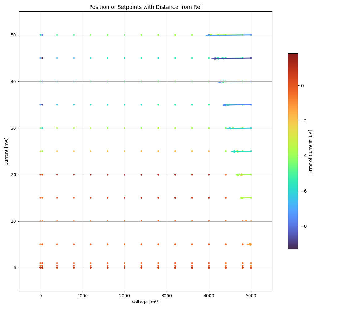
full range: 0 to 5V, 0 to 50 mA
limited range: 1 to 3.9 V, 3uA to 40mA
Harvester - low current measurement-limit
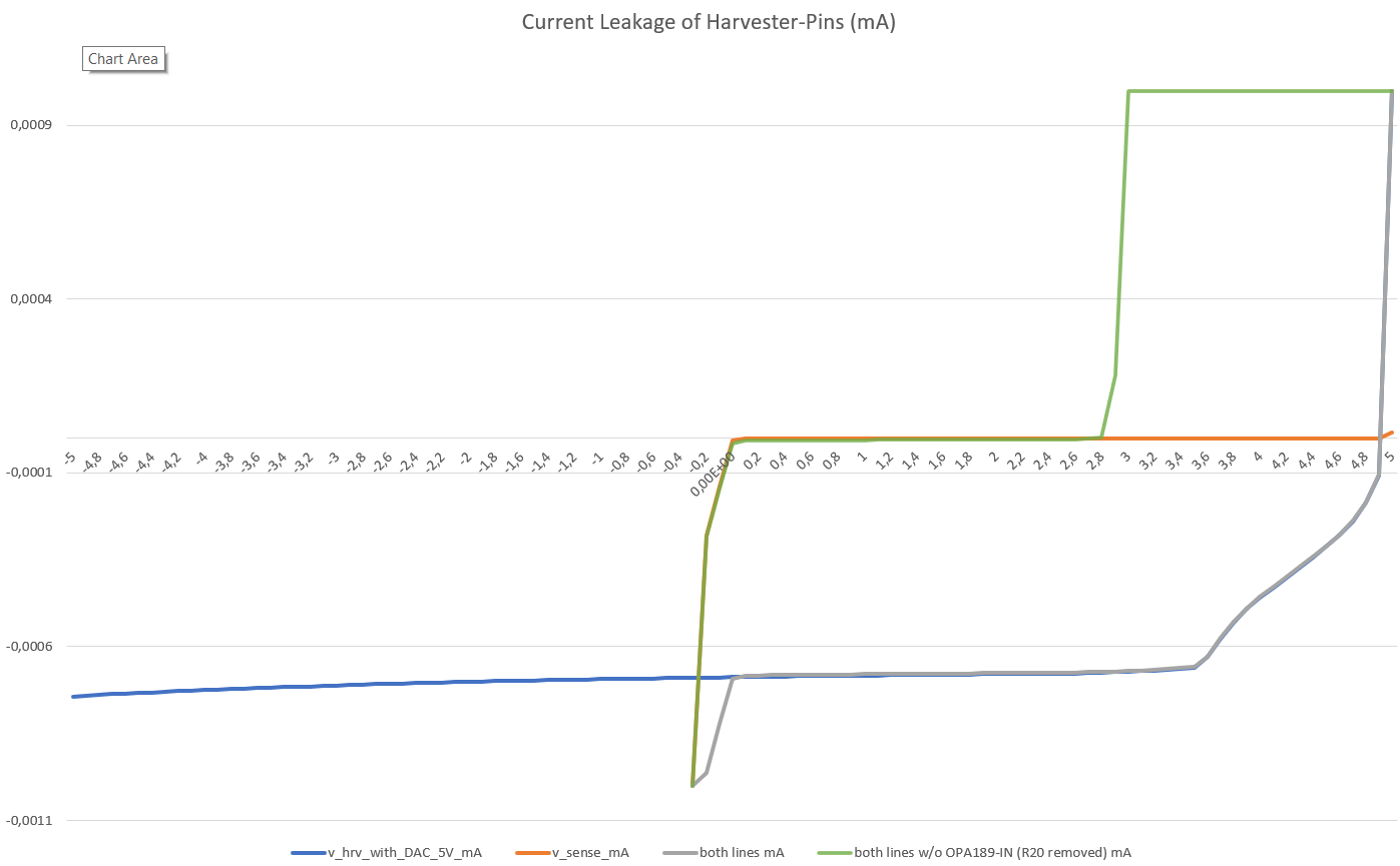
draining below 1-2 uA ⇾ voltage seems to invert (SMU reports -0.3V), not caring about the set-voltage of the DAC
adc-current values are equal to “zero”
diode blocks (later tests show 2nA reverse current), because voltage at cathode (opAmp-Out) is similar high to DAC-Voltage
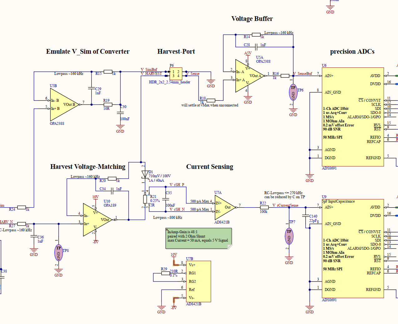
something seems to reverse leak current ⇾ tldr: it is the OPA189 Negative Input Pin
OPA189 input can leak max +-1 nA (input bias current) and differential input impedance is 100 MOhm (100nA to 10V)
AD8421 inputs can leak max 2x +-500 pA, tests show < 1 nA
OPA2388 input can leak max +-400 pA (spec), tests show < 1 nA
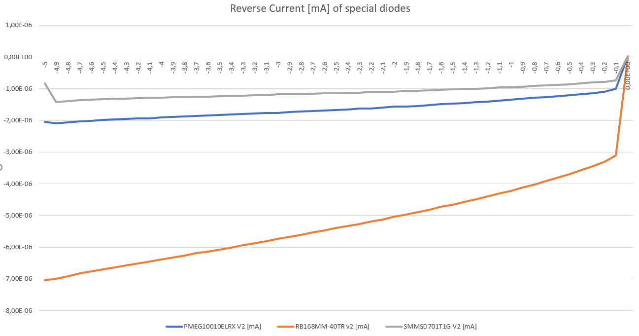
diode is rated for 40 nA but shows in tests 2 nA @ 5V (see picture below)
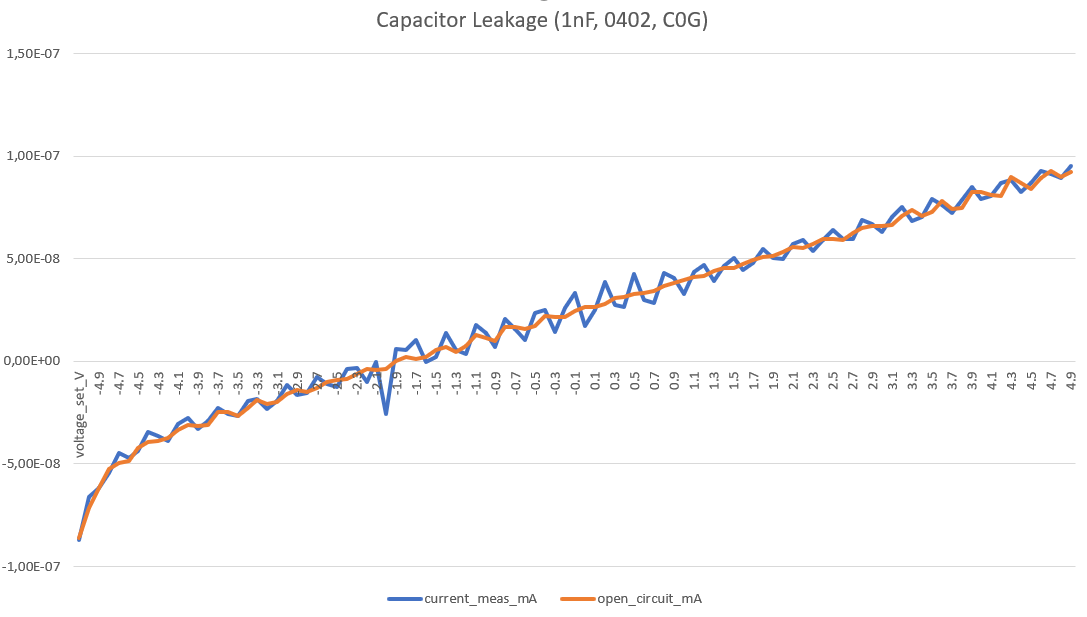
capacitor C34 (Opa-Feedback) could leak ⇾ tests show < 1 nA @ +-5V-Range (see picture below)
and the op189 output ⇾ not relevant due to safe diode and capacitor
removing R20 stops the leak ⇾ hint at OPA189 or cap C34
removing C34 changes nothing ⇾ final clue for OPA189
that may never occur with a real harvesting source (or work as a hard-to-detect offset)
baking pcb off (80 °C, 30min) had no effect (mentioned in datasheet)
this leakage is often not existent when SMU is freshly started for the day ⇾ firmware-update to 3.4.0 (2021-04, from 3.2.2 2016-04) did not help
see profile 25, whole voltage range, down to 0 uA
changing R20 (Feedback-Lowpass) to 100R or 10k does not change behavior
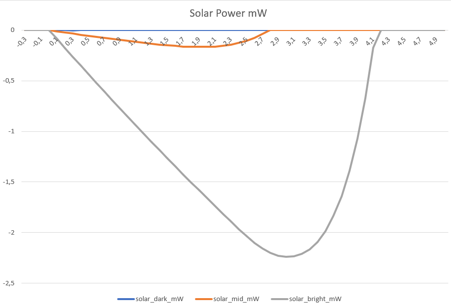
tests with solar-cell (SM101K09L) shows that 2uA is near to dark environment
old TODO:
reverse position of diode and shunt
OPA189 speaks of (8.3.3) input bias current clock feedthrough (switching input to correct intrinsic offset)
⇾ it seems to be the “zero-drift” feature of OPA189 that gets triggered wrongly
worst outcome: 1-2 uA offset in measurement
Update: this problem went away by using another py-lib for the SMU (and cleaner, more explicit init)
Schematic of Harvester v2.3
Current Leakage for Capacitor 1nF (C0G)
Current Leakage for Harvest Port
Power from Solar Cell (SM101KO9L) in various conditions
Diode Comparison
PMEG10010ELRX
rated for (extremely low leakage current) 4 nA @ 10 V & 25 °C and 40 nA (typical, 150 nA max) at 100V & 25°C
measurement: -5 V result in 2.1 nA at room temperature
seems the safest bet, because datasheet promises the spec
SMMSD701T1G
rated for ~ 8-9 nA @ 6-12 V & 25 °C (curves in datasheet)
measurement: -5 V result in 1.4 nA at room temperature
lowest leak-value but not distinguishable from PMEG-Version in Frontend
RB168MM-40TR
rated for 50 (typical) to 550 uA reverse current @ 40 V
curves in datasheet show IR @ 5 V, 25°C at around 10 nA, up to 1000 nA at 75°C
measurement: -5 V result in 6.9 nA at room temperature
the first two diodes are fine!
⇾ see media_v23/profiler_smu_diodes.csv
Reverse Current of Diodes
Harvester - Current Measurement
2R-Shunt, Gain x48 ⇾ 10R Shunt, Gain x10
no significant effect from profiler
keep synced to emulator to save parts
keep 2R-Shunt
Lowpass between InAmp and ADC
100k results in high offset of > offset of 11’800 n for 0 nA (ADC input seems to be raised by ADC itself)
1k results in offset = ~ 182 n (Good) and lower Noise, mostly on full range (3-14x better)
100R seems to worsen limited area (slightly), but improve full range (almost x2)
Cap was varied to match 80 - 160 kHz lowpass, but influence is minimal
0R caused trouble with voltage dependent current reading +-10uA from 0 to 5V
33R / 10nF is fine, limited range gets minimal worse, but full range improves
buffered shunt (parallel cap C35)
470 nF instead of nothing: 10 - 20% improvement on limited and full range
nothing instead of 100 nF: 5-10 % worse on full range, minimal better on limited range (but with 100 nF seems the better bet)
100nF instead of nothing: ~10% improvement on both ranges
later tuning showed almost no influence of the cap (0, 10, 100nF) only max_error gets limited in profiler
10nF does suffice!
buffered inputs (Caps on V_HRV and V_Sense)
adding 2x 100nF is ~ 10 % worse
remove
different diode (try alternatives)
no significant effect between new (and better) SMMSD701T1G-Diode and (current) PMEG10010ELRX
slower OpAmp-Feedback
R20, 10k instead of 1k or 100R: 10-12% improvement for both ranges, but only static case (lowpass 16 kHz)
later tuning showed that 100R (compared to 330, 1k) are preferred, because OpAmp has to be fast (for the nonlinearitiy, ie. in voltage sweeps
faste OpAMp is better, as long as stable
DAC to OpAmp Connection
slower response helps measurement
current 1k & 1nF are fine ⇾ 9 us risetime from rail to rail (same with 200R, 1nF)
100R & 10nF seem to perform a bit better
shield
is not hurting the measurement, but helps with noisy environments
set DAC-Ref-voltage to external A5V
current-reading improvement, while voltage worsened? but error stayed after reversing the change
TODO: investigate
Harvester - Voltage Measurement
bigger shunt Resistor is 5-10% worse
C35 parallel to shunt is better than no Cap, 100 nF is fine, 10nF also
R16 before ADC-V is better smaller, but filtering is also
Cap before ADC-V is better, 10nF compared to nothing brings 10 % improvement
R18 before OpAmp was 1k, removal brings 10 % improvement
Caps 100nF on Pinheader-Inputs is 5-10 % worsening
R20 low ⇾ Voltage-Matcher should be rather fast (better for V_meas, worse for C_meas)
DAC-Lowpass is fine, lower Freq helps measurement
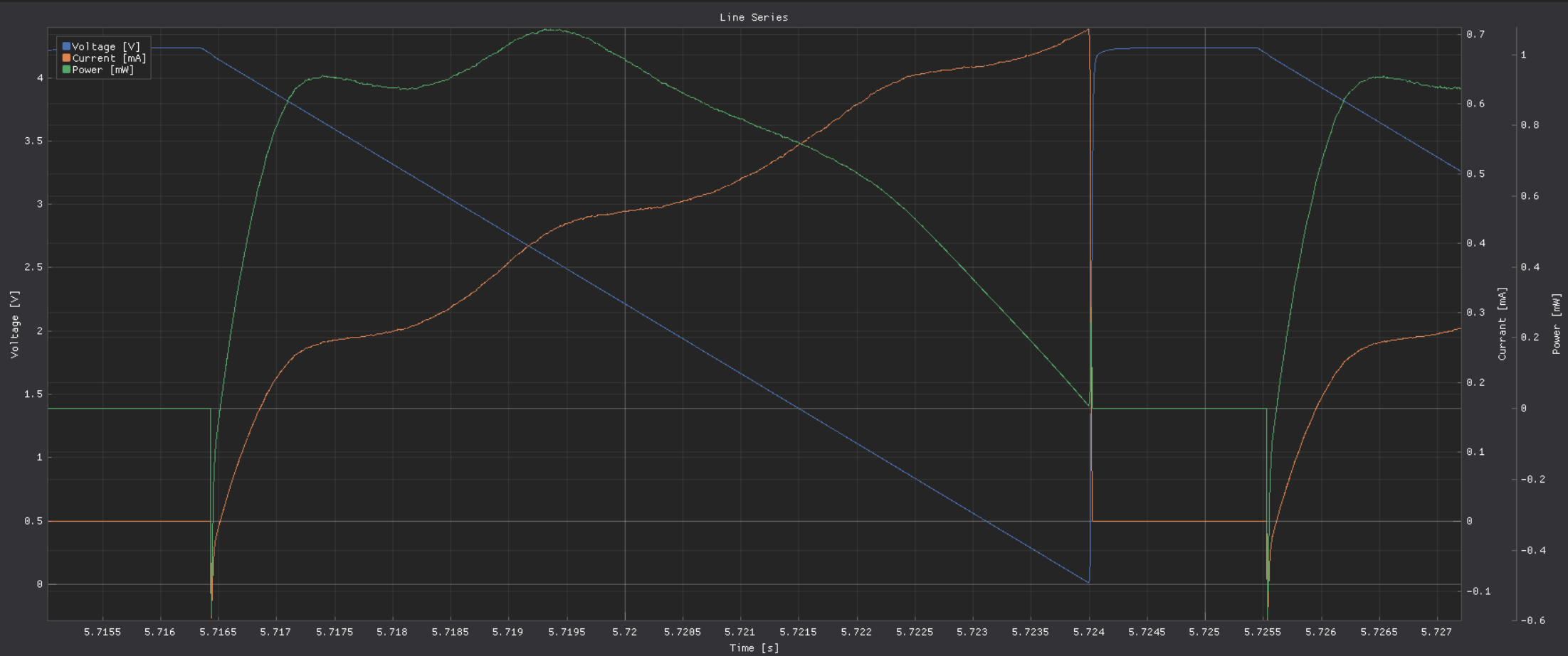
Without ShuntBuffer the current reading may be noisy (1k OpAmp Feedback, 0nF Shunt-Buffer)
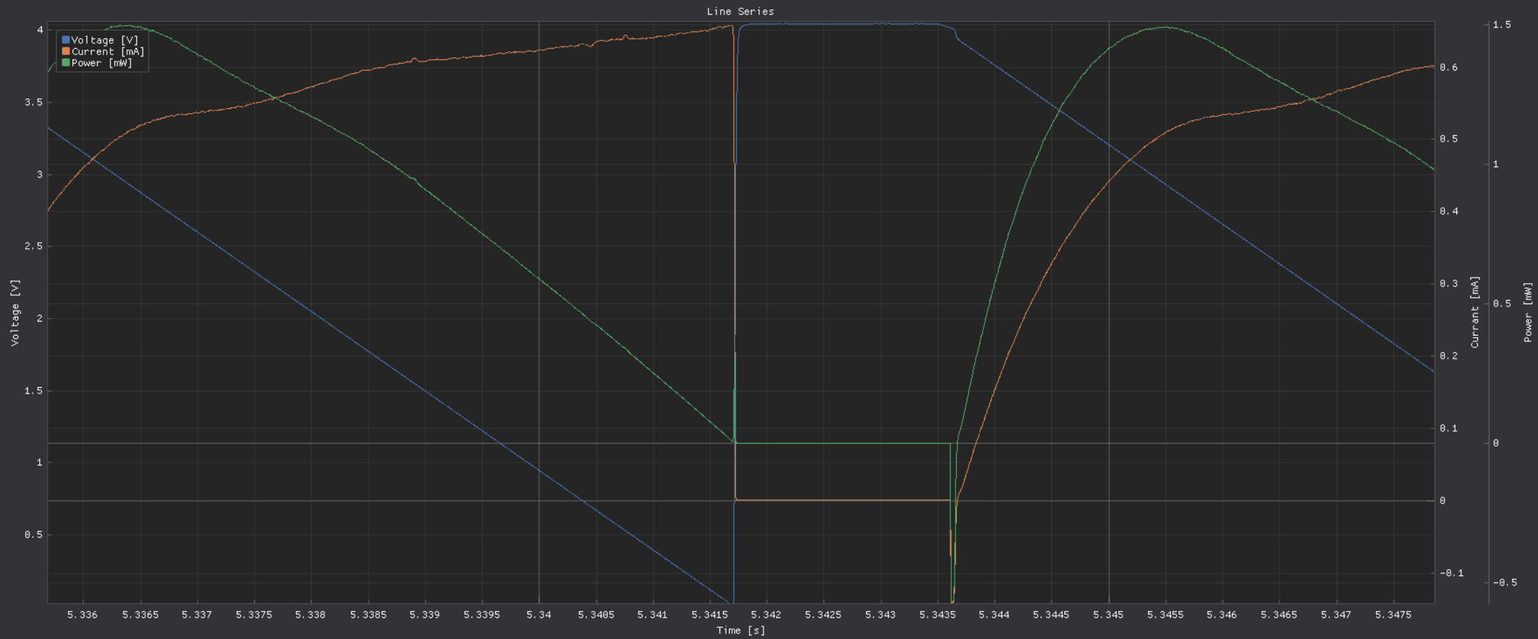
Improvement with 10nF ShuntBuffer
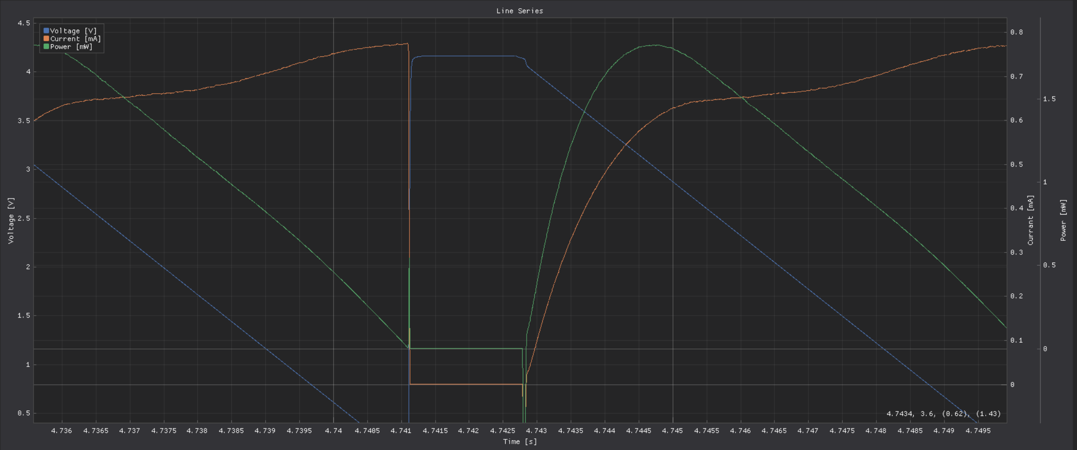
OpAmp is stable enough to lower FB to 100R ⇾ this gets rid of the nonlinearity in the sweep (area where open circuit voltage meets voltage ramp):
Emulator
can’t produce 5 V with 50 mA
even at 0 mA the limit of 5 V is not completely on point,
at 50 mA around 4 V are usable without large error
⇾ seems to be fine for modern electronics
2 R Shunt resistor is responsible for 100 mV drop (50 mA)
R10 from 100k changed to 0R ⇾ offset still around 15.x, similar as with 33R in harvester
5V-Voltage regulator needs at least +1V Input ⇾ raise 6v_Rail from 5.4V to 6.17V ⇾ Emulator improves to 50mA @ ~4.28V
Opa388 seems to be worse than the Opa189 ⇾ switch to this one
BB-Powered Mode
turning cape on when on BB-USB-Power crashes the system
5V_BB (P9-7/8) gets connected to 5V Line with inductor and large 1mF Cap
most inductors show only minimal influence ⇾ remove them
more capacity on power-line is better (A5V is most significant), see traces below
No additional Buffering on A5V-Line
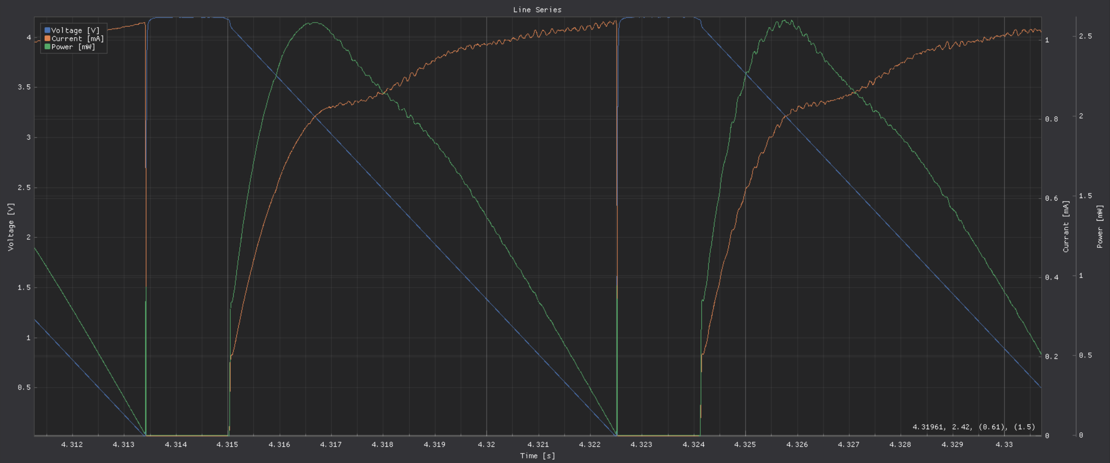
1mF Cap on A5V line - less noise!
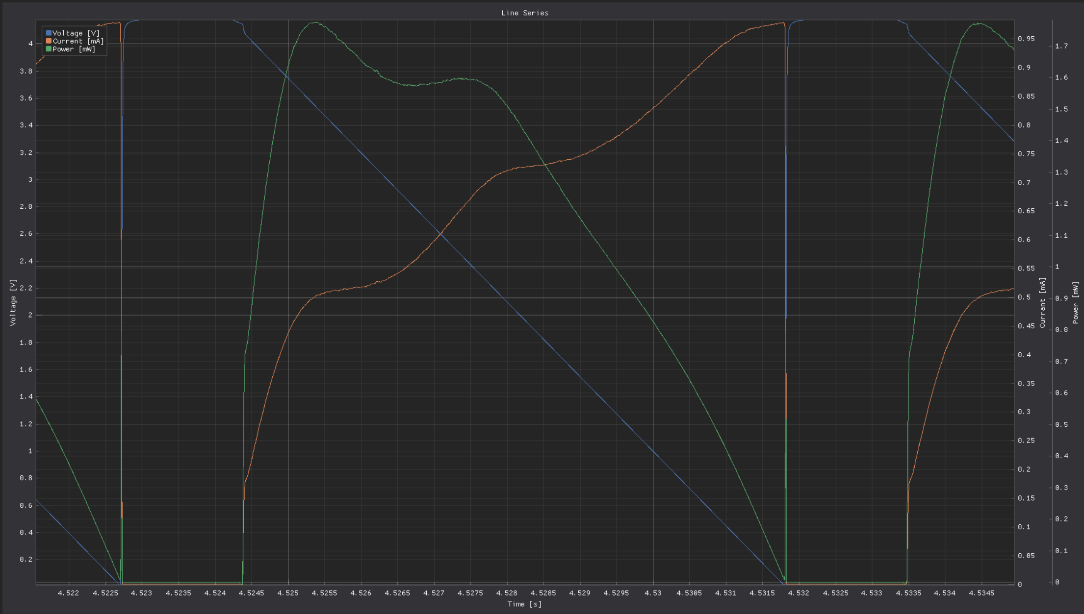
Stabilize ADC-Readings
Plan: work through datasheet for more design guideline hints
ADC ADS8691
use X7R caps for V_in and ref-pins
low impedance sense-input
InAmp AD8421
VS with 100nF + 10uF
RG with minimized capacitance
connection to ADC: 100R + 3nF
ref-voltage with OP1177, with 5k feedback, no C, 10 uF buffer for OpAmp Input
low impedance connections, input can be buffered
OpAmp Opa189
same as Opa388
seems more stable than opa388, fb-cap can be omitted
OpAmp Opa388
shield / isolate from air-currents and heat-sources
place 100nF directly to pwr-in and use groundplane
DAC8562
AVdd with 100pF, 1nF, 100nF, 1uF
VRef-Buffer, higher capacitance raises noise floor?
internal reference is more noisy (1.4 to 3x less noise with perfect external ref) ⇾ fail because voltage has huge error (current got more stable though)
LDO LP2989
bypass cap 10nF C0G or NP0
provide VIn >= VOut + 1V
Inverter LT3487
Thermal Pad (GND) low impedance, many vias
bypass with X7R
negative channel >= 10uF, pos Channel > 4.7 uF
phase lead caps for dampened load response (10-33pF parallel to FB-Res)
input can start at 1uF
Noise-Reducing Experiments
ADC: R10 33R, C62 10nF lowpass, 482kHz ⇾ not much difference?
R8, 5k OpAmp FB from 2k
50 mV from std-dev 2800-4000-26, to 25-52-25
2V from 31-60-31 to 25-56-30
C3, 1nF OpAmp FB remove
50mV completely unstable
C5, remove 1uF DAC_Ref-Buffer
DAC_Ref to A5V ⇾ 1.4 to 3x less noise expected
2V to std 22-55-29
current-channel is improving a bit overall (>5%), but with 20% larger max-errors
voltage-channel is 25-100% worse (mean)
HRV
R20 back to 1k
R22 to 33 R, C140 to 10nF
R27 to 33 R, C36 to 10nF
R27 back to 100 ⇾ 100R & 10 nF ⇾ 160 kHz
R27 1k, C36 1nF ⇾ same 160 kHz
C35 Buff, 0nF, 10nF, 100nF
R20 FB smaller 1k, 330R, 100R, 33R
100R - 50 us for 0 to 5V, significantly smaller bump between ramp and open voltage
openC still 50us, even with reduced R27/200R ⇾ Scope shows 9us risetime at diode (200R)
1k (R27, back to normal) still 9us risetime on scope
cross-supply DAC
emu
DAC-out 33R, 10nF
Level-Translators
speed for programming should exceed 1 MHz
test shows safe flanks for ~ 200 kHz
setup
Level translator: 74LVC2T45GS
Analog Switch: NLAS4684
Risetimes for different configurations:
1k + NLAS ⇾ 1000 ns ⇾ 434 pF tracecapacity calculated
330R + NLAS ⇾ 340 ns ⇾ trace-capacity unchanged
1k + removed 100k PU ⇾ 1000 ns ⇾ trace-capacity unchanged
1k + removed NLAS ⇾ 37 ns ⇾ 16 pF capacity, Trace ~20mm, w=0.2mm
1k + removed NLAS + trace to PinHeader ⇾ 45 ns ⇾ 19.5 pF (~40 mm Trace, w=0.2mm)
capacitance
scope probe = 13 pF
Line-Capacitance = 1 pF / 7mm
NLAS-Capacitance = 414 pF ⇾ both outputs behave a bit different ~ 10 % off
C_off = 104 pF (typical), NLAS-Datasheet @ 1 MHz
C_on = 330 pF (typical), NLAS-Datasheet @ 1 MHz
Pin-Capacitance of uC, and drive capabilities
nRF52 3-4 pF, gpio current is 14/15 mA
msp430 5pF, gpio current is 6 mA
AM335x 5.5 pF, gpio current is 8 mA
constraints for the next analog switch
VIn >= 5V
capacitance << 100 pF
leakage << 100 nA
https://www.mouser.de/c/semiconductors/switch-ics/analog-switch-ics/?mounting%20style=SMD%2FSMT&number%20of%20channels=2%20Channel~~7%20Channel&instock=y&rp=semiconductors%2Fswitch-ics%2Fanalog-switch-ics%7C~Number%20of%20Channels&sort=pricing
https://www.mouser.de/c/semiconductors/switch-ics/analog-switch-ics/?configuration=1%20x%203PDT~~1%20x%204PDT%7C~1%20x%20DPDT%7C~2%20x%20DPDT~~2%20x%20DPST%7C~2%20x%20SP4T~~2%20x%20SPDT%7C~3%20x%20DPDT~~3%20x%20SPDT%7C~4%20x%20SPDT%7C~6%20x%20DPDT~~8%20x%20SPDT&mounting%20style=SMD%2FSMT&instock=y&sort=pricing&rp=semiconductors%2Fswitch-ics%2Fanalog-switch-ics%7C~Configuration
Vc = Vs * (1 - e^(-t/(RC))); C = t * log(e)/(Rlog(Vs/(Vs-Vc))); tau = RC; fc = 1/(2piRC);
Contestants for Switch-Replacements
roughly ordered from cheap to expensive
Contestants SPDT or DPST, naming is not precise
NLAS4684, 5.5V In, ~330 pF, 1-2 nA Leakage, < 1 Ohm ⇾ perfect for analog voltage supply to targets
FSA2258, 4.3V In (max 5.5V), ~ 50pF, 10 nA Leak ⇾ using 5V is too risky
DIO3712, 6V In, ~ 10pF, max 2 uA Leak ⇾ typical leakage unknown, too risky
PI5A4158, 5.5V In, ~ 34pF, 40 nA Leak ⇾ strange package 1x3mm
DIO1269, 5.5V In, ~ 120 pF, 20nA Leak
DG2735A, 6V In, ~ 120pF, 10 nA Leak,
NLAS3158, 5.5V In, 19 pF, 100nA Leak,
DGQ2788, 6V in, 26pF, 1.2uA Leak,
FSA2275, 6V in, ~ 25pA, 1uA Leak
PI5A100Q, 4SPDT, <6V, 10 Ohm, 18 pF, 80nA max, 70pA typ !!!! (5x5mm QSOP16)
Contestants for SPST (>= 4x, one EN is fine)
74HC4066BQ, 4SPST, 50 Ohm, <=11V, typical 8pF, 1uA max Leak
HEF4066B, 4SPST, <15V, 200nA max, 8pF, 350-2500 Ohm
74HCT4066, 4SPST, 50 Ohm, <=5.5V, typical 8pF, 1uA max Leak
CD4016
SN74AHC4066, <5.5V, 38-180 Ohm, 100nA max, 6 pF
NLVHC4066, <12V, 100 mA max, 15 pF, 70 Ohm,
CD74HCT4066, 5.5V, 2 uA max, 10 pF
SN74LV4066, 4SPST, 31-100 Ohm, <= 5.5V, typ. 6 pF, typ 0.1 uA leak, max 1 uA
CD74HC4316, 4SPST, 45-180 Ohm, <= 6V, 10 pF max, 100nA leak
TMUX1511, <= 5.5V, 6 pF max, 50 - 100nA leak max, 0.03nA typ, 2-4 Ohm, proper characteristic plots (RARE!!)
CD74HC4016, similar to HC4316
MC74HC4067, <6V, 800nA - 8uA leak max, 10pF or 45pF
DG2501DB, <5.5V, 1nA max leak, 8pF typical, (similar: DG2502, DG2503), 100 Ohm typical, 4Channel, ~ 1.2€, (4x4 BGA, 0.35mm Pitch)
DG442 / DG441, 16V max, 1nA leak max, 15 pF typ, 130 Ohm max (OK, but big package)
DG611 / DG612, 4SPST, 16V max, 6nA max, 230 Ohm, 7 pF, (mini QFN16, 3x2mm, .4mm pitch, )
DG2034, 5.5V, wrong config ⇾ vishay offers low leakage and bandwidths up to 1 GHz
Digital bus switches, 4-8 bit
SN74CBT3125 (312x), 4bit, 5.5V, 16-22 Ohm, 4pF, no Leakage noted ⇾ bad datasheet
SN74CBT3245, 8bit 1EN, 5.5V, 8-12 Ohm, 14 pF, 10uA leak?
SN74CBT6845, 8bit, precharged ports
SN74CBT3244, 8bit, similar to 3245
QS3125, 4bit, 1uA leak max,
SN74CBT3345, 8bit, 1uA leak max?
PI5C3245, 8bit, 1uA leak
SM74CBT3126, high leakage
FST3125, 1uA leakage
… even most expensive one had high leakage
LSF0108 - AutoDir Level Translation with full
Left Side of LSF
74HC4066 ⇾ typical 8 pF
33 R Line, 10 k PU
80 mm Trave ⇾ ~ 13 pF
AM335x ⇾ 5.5 pF
LSF0108 has max 12.5 pF (on), 6 pf off
Right Side of LSF
1 k Line, 10 k PU
PI5A100Q ⇾ 18 pF
50 mm Trace ⇾ ~ 10 pF
Target ⇾ 5 pF
Old right Side: NLAS with > 330 pF